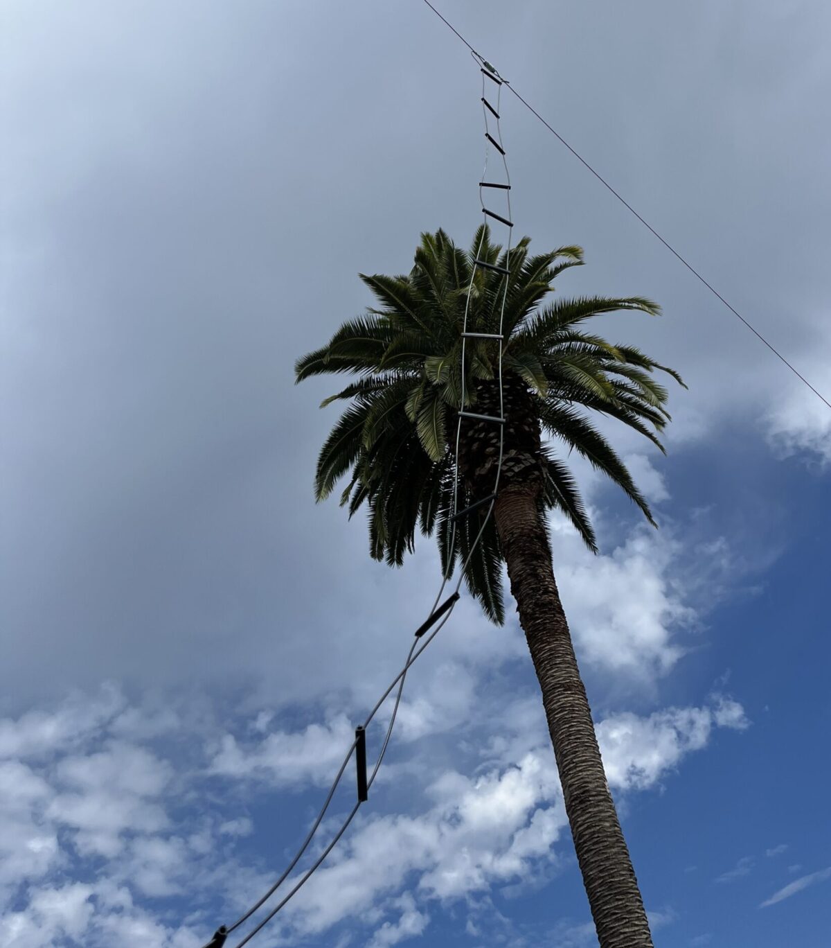
I have a very space constrained area to put up antennas in so I am frequently on the lookout to optimize what I can do in the space I have. I have always wanted to try a nonresonant dipole (aka doublet) after having fallen in love with horizontal dipoles. The main problem is loss at high SWR. Luckily there is an option, open wire line. Open wire line is the least lossy transmission line amateur operators have at their disposal. They can be tricky to route but was well worth the effort in my case as it is still cheaper than high quality low loss coax. Due to the low height of 7.5m AGL available to me for the antenna, I chose to make an antenna for 10-20m so that the take-off angle would still be good for 10-15m. I got 40m as a bonus band and it seems to work well for digital mode DX and okay for SSB NVIS due to the low height.
Brief Theory:
I first did a bunch of research into how I was going to do it. I came upon these very helpful links. This was enough information to get me going.
- Some (Old) Notes on Home-Brew Parallel Transmission Lines – L. B. Cebik, W4RNL
- Homemade Open Wire Feedline – A1AEX
- My Top Five Backyard Multi-Band Wire HF Antennas – L. B. Cebik, W4RNL
I’m not going to rehash the nonresonant dipole; you can read about it in the link above if you’d like some more info. What I will detail is the somewhat novel approach I took to building mine to fit my constrained space. I used AB3AP’s Matlab code in Octave to determine my leg and transmission line lengths to avoid even fractional wavelengths on the bands of operation which result in extremely high impedance (untunable) nodes. AB3AP’s code is intended to be used to calculate nonresonant end fed antennas but the lengths are perfect for what we need. Just make sure to use the length as the measure of one leg or length of transmission line. I will note that it would be best to not just use the charts on the webpage. Use the code to calculate the lengths for the bands you desire to operate on.
Tractor Supply Shopping List:
- American FarmWorks 4in Fin Tube Insulators
- American FarmWorks 5in Nail-on Extender Insulators
- American FarmWorks Crimp Sleeves (Optional)
- American FarmWorks Sleeve Crimper (Optional)
- American FarmWorks Jumbo Corner Insulators (Optional)
- American FarmWorks 14 AWG Aluminum Fence Wire (Optional)
Ham Radio Outlet Shopping List:
- Davis RF PS-13 PE Jacket CCS 13 AWG Stranded Antenna Wire (Optional)
- MFJ-16C06 Ceramic Dogbone Insulators (Optional)
General Construction Notes:
I chose to use fancy ceramic dogbones and Davis RF PolyStealth wire but those are entirely optional. I listed some cheaper options in the shopping list and I don’t believe using them would affect the performance significantly. Additionally, I use aluminum crimp ferrules to secure my wire antenna ends to insulators. This is also optional if you have some other favorite way to do it. I made my antenna two continuous conductors to make the most robust antenna I could but this is also optional.
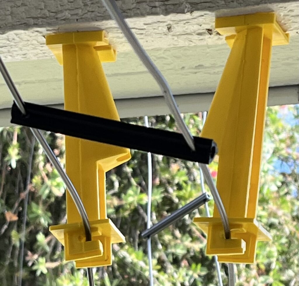
I, like A1AEX, chose to set my spacers at 12″. This is also entirely optional the goal is to keep the parallel wires evenly spaced and prevent them from twisting over each other. It is entirely up to you to set the spacing as you see fit. I did not however choose to fill the spacers with hot melt adhesive as A1AEX did. I have not yet seen any negative consequences to omitting this step
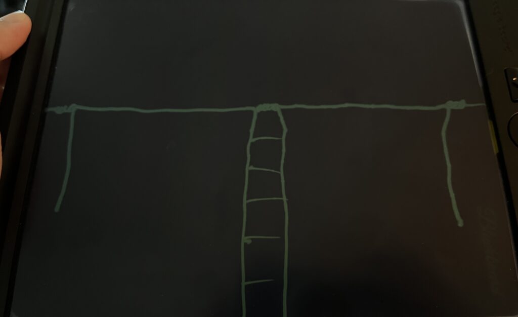
Another peculiarity of the way I constructed this antenna is that for it to fit, I had to bend the ends of the antenna downward as depicted in the crude drawing above. It is not to scale; the ends are shorter. Most of the significant radiation happens close to the feedpoint so this doesn’t affect the radiation pattern all that much. I will make a new post when I reconstruct this antenna to include a forgotten end loading technique resurrected by W5NVY and the ORI team.
OWL Spacer Construction:
Just measure down about 1/4″ and drill a hole small enough to be able to get the wire through but not so big that the tube isn’t pretty snug to the wire. I did not cut my tubes as A1AEX did. I slid the spacers on like beads.
Routing:
I have seen people list an amazing range of distances you should keep open wire line from other objects. I have not had an issue using these 5in spacers but YMMV depending on the material of the object you affix these to and whether or not the object runs parallel or perpendicular to the transmission line. These worked perfectly for my installation. I plan to use them for a longer run once I reconfigure my operating location.
Tuning:
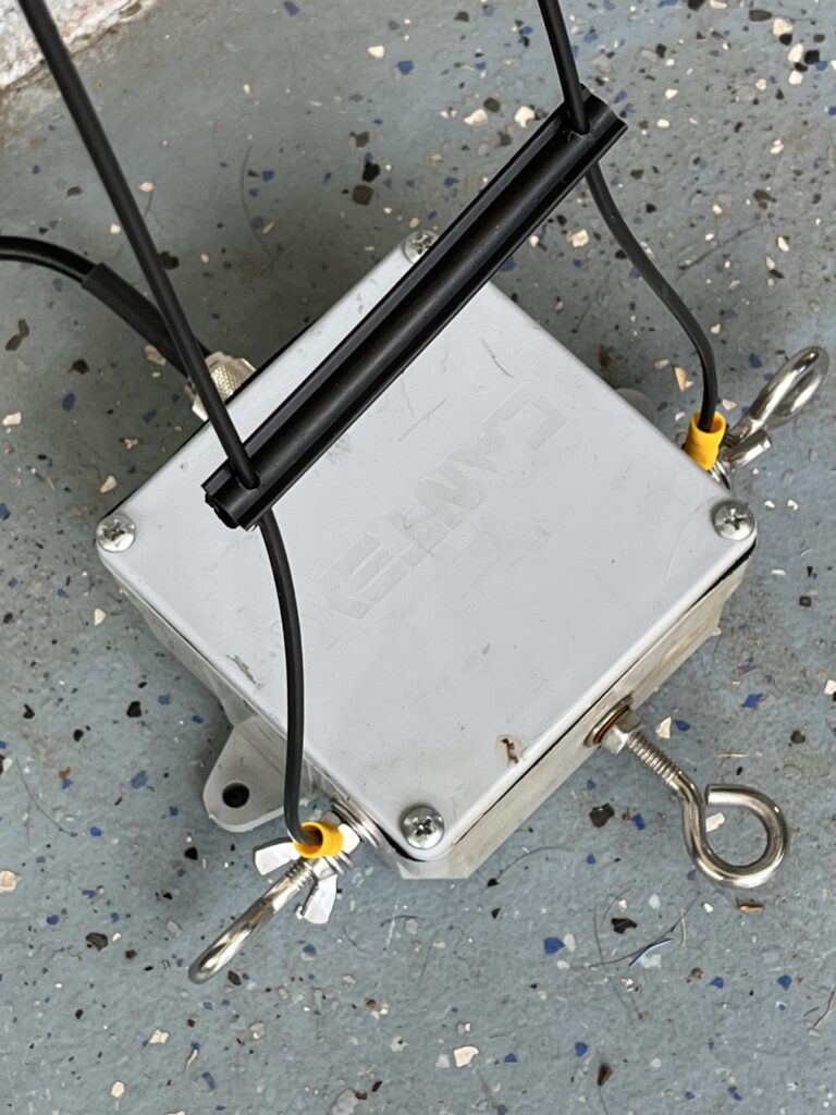
If you are going to use an automatic ATU like an LDG make, I think the best option is to build a heavy duty high impedance K9YC design 1:1 Guanella choke at the transition and an LMR400 coax jumper to the tuner. You will likely need a wide range tuner if you follow my instructions to make an antenna that covers 10-80m. We are relying entirely on the antenna tuner to transform the wide range of impedances presented due to the wide latitude of frequency of operation. If you want all the bands, you need a wide range tuner; your internal tuner will not cut it.
Additional Thoughts:
So far the antenna has been great and appears to have very similar radiation patterns as evidenced by PSKreporter. The antenna is performing at least as well as all of my coax fed monoband dipoles hung at the same height and in the same space but now I am QRV on six bands. When I redo the antenna to include the novel end loading technique I will try to make the antenna even more broadband to include 80, 30 and maybe even 6m. One additional note is that I have this dipole hung roughly North to South. This is highly advisable for optimal global coverage at mid latitudes.